-
×
 STC-3028 Humidity and Temperature Controller (12VDC)
1 × ₨2,500
STC-3028 Humidity and Temperature Controller (12VDC)
1 × ₨2,500 -
×
 5 Inch Seven Segment (Cathod)
1 × ₨250
5 Inch Seven Segment (Cathod)
1 × ₨250
Subtotal: ₨2,750

 STC-3028 Humidity and Temperature Controller (12VDC)
1 × ₨2,500
STC-3028 Humidity and Temperature Controller (12VDC)
1 × ₨2,500 5 Inch Seven Segment (Cathod)
1 × ₨250
5 Inch Seven Segment (Cathod)
1 × ₨250Subtotal: ₨2,750
 STC-3028 Humidity and Temperature Controller (12VDC)
1 × ₨2,5005 Inch Seven Segment (Cathod)
1 × ₨250
STC-3028 Humidity and Temperature Controller (12VDC)
1 × ₨2,5005 Inch Seven Segment (Cathod)
1 × ₨250Subtotal: ₨2,750
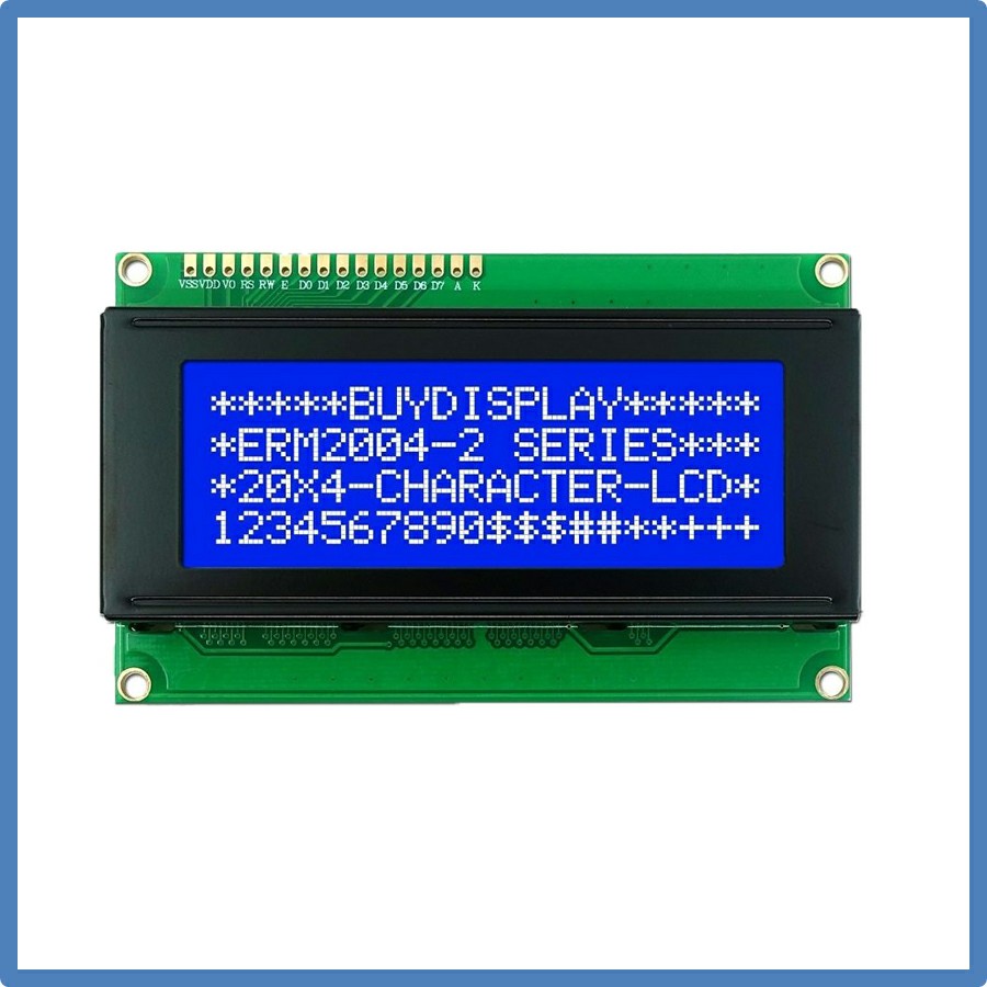
Pin Configuration
1 Ground
2 VCC
3 Contrast adjustment (VO)
4 Register Select (RS). RS=0: Command, RS=1: Data
5 Read/Write (R/W). R/W=0: Write, R/W=1: Read
6 Clock (Enable). Falling edge triggered
7 Bit 0 (Not used in 4-bit operation)
8 Bit 1 (Not used in 4-bit operation)
9 Bit 2 (Not used in 4-bit operation)
10 Bit 3 (Not used in 4-bit operation)
11 Bit 4
12 Bit 5
13 Bit 6
14 Bit 7
15 Back-light Anode(+)
16 Back-Light Cathode(-)
Check out our Blog on LCD Interfacing with Arduino UNO
https://piees.blogspot.com/2020/08/162-161-204-lcd-interfacing-using.html


